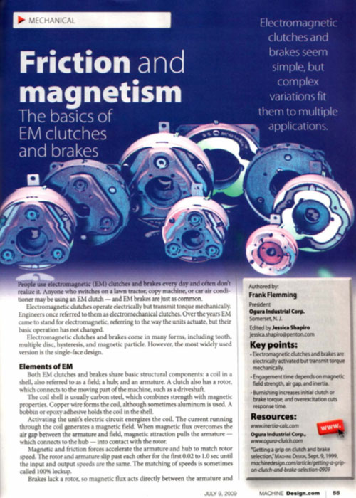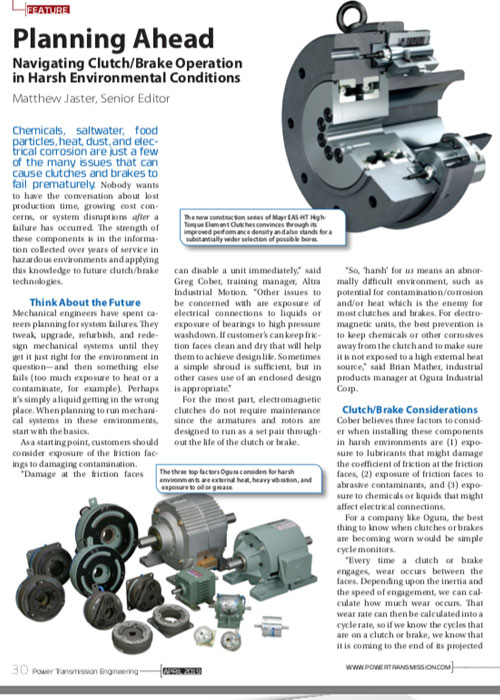
There are many types of electromagnetic brakes (tooth, multiple disc, hysteresis, magnetic particle). The most widely used version is the single face design. Electromagnetic brakes operate electrically but transmit torque mechanically. This is why they used to be referred to as Electro Mechanical clutches and brakes. Over the years EM became known as electromagnetic verses electro mechanical referring more about their actuation method verses physical operation. Since electromagnetic brakes started becoming popular, over seventy years ago, the variety of applications and brake designs has increased dramatically but the basic operation of the single face electromagnetic brake still remains the same.
Think of the coil shell as a horseshoe magnet having a north and south pole. If a piece of iron contacted both poles a magnetic circuit is created. When power is applied a magnetic field is created this field (flux) overcomes the air gap between field and the armature. This magnetic attraction pulls the armature in contact with the brake field face. The friction and the strength of the magnetic field, is what causes the rotational motion to stop. Almost all of the torque comes from the magnetic attraction and coefficient of friction between the steel of the armature and the steel of the rotor or brake field. But for many industrial clutches or brakes, friction material is used between the poles. The material is mainly used to help decrease the wear rate. But different types of material can also be used to change the coefficient of friction for special applications. For example if the brake was required to have an extended time to stop or slip time, a low coefficient material can be used. Conversely, if the brake was required to have a slightly higher torque, a high coefficient friction material could be used.
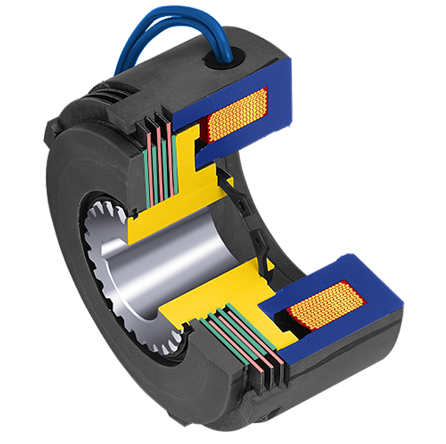
Copper (sometimes aluminum) magnet wire used to create the coil which is held in the shell either by a bobbin or by an epoxy / adhesive. For most industrial brakes, friction material is then placed over the coil and is set between the inner and outer pole. The friction material is flush with the surface of the brake because you want to have metal to metal contact between the coil shell and the armature. (Some people mistakenly look at electromagnetic brakes and assume that it is already worn down since the friction material is flush but that is not the case.)
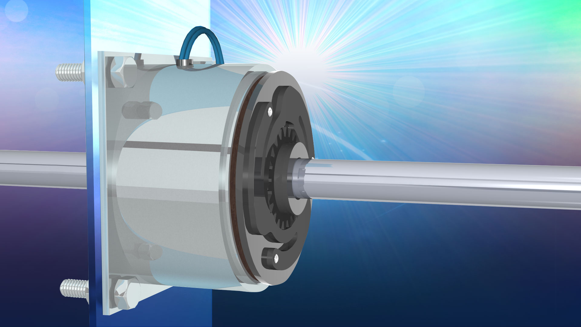
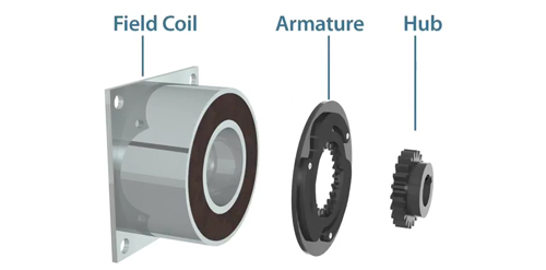
In a brake, there are only three main parts; field, armature and hub (which is the input on a brake). Usually the magnetic field is bolted down to something solid (or has a torque arm). So when the armature is attracted to the field the stopping torque is transferred into the field housing, decelerating the load. This can happen very fast. But brake time to stop can be controlled by the amount of voltage/current applied to the field.
The strength of any magnetic field could be changed by changing both wire size and the amount of wire (turns). EM brakes are similar and they use a copper wire (sometimes aluminum) coil to create a magnetic field.
The fields of EM brakes can be made to operate at almost any DC voltage and the torque produced by the brake will be the same as long as the correct operating voltage and current is used with the correct brake. If you had a 90 volt brake a 48 volt brake and a 24 volt brake all being powered with their respective voltages and current, all would produce the same amount of torque. However if you took a 90 volt brake and applied 48 volts to it you would get about half of the correct torque output out of that brake. This is because voltage/current is almost linear to torque.
A constant current power supply is very important if you want accurate and maximum torque from a brake. If a non regulated power supply is used the magnetic flux will degrade as the resistance of the coil goes up. Basically the hotter the coil gets the lower your torque will be.

It’s a reduction by about an average of 8% for every 20°C. If the temperature is fairly constant and there is enough service factor in the design for minor temp fluctuation, slightly oversizing the brake can compensate for flux degradation. This will allow usage of a rectified power supply which is far less expensive than a constant current supply.
Based on V = I × R, as resistance increases, available current falls. An increase in resistance often results from rising temperature as the coil heats up, according to: Rf = Ri X (234.5 + tf/ (234.5 + tf). Where Rf = final resistance, Ri = initial resistance, 234.5 = copper wire’s temperature coefficient of resistance, Tf = final temperature, and Ti = initial temperature.
There are two engagement times to consider in initial electromagnetic brake action. The first is the time it takes for a coil to develop a magnetic field strong enough to pull in and attract an armature. Within this scenario there are two factors affecting this. The first one is the amount of turns in a coil which will determine how quickly a magnetic field is generated. The second one is the air gap which is the space between the armature and the face of the brake. This is because the magnetic lines of flux diminish quickly in air. The further away the attractive piece is from the coil the longer it will take for that piece to actually develop enough magnetic force to be attracted and pull in to overcome the air gap. For very high cycle applications floating armatures can be used that rest against the brake face. In this case the air gap is zero but more importantly the response time is very consistent since there is no air gap to overcome. Air gap is an important consideration especially with a fixed armature design because as the unit wears over many cycles of engagement the armature and the brake face will wear creating a larger air gap which will change the engagement time of the brake. In high cycle applications where registration is important even the difference of 10 to 15 milliseconds can make a difference in registration of the driven material. Even In a normal cycle application this is important because a machine that was at one time good, can eventually see a “drift” in its’ registration.
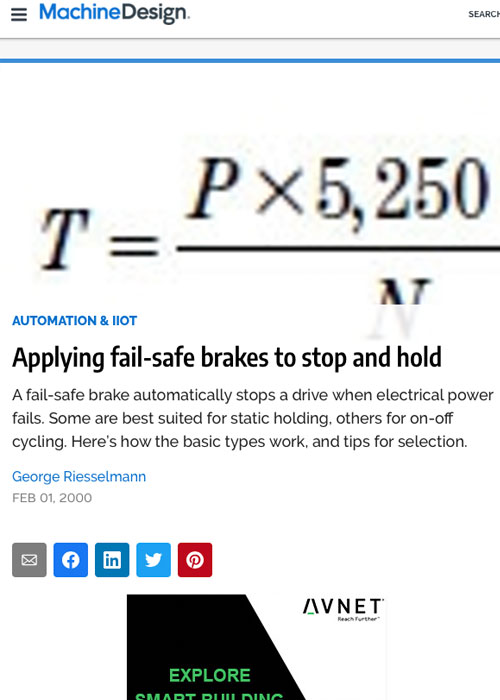
Second factor in figuring out response time of a brake is actually much more important than the magnet wire or the air gap. It involves calculating the amount of inertia that the brake needs to decelerate. Many customers refer to this as time to stop. In reality this is what the end customer is most concerned with. Once it is known how much inertia is required for the brake to start or stop then the appropriate size of brake can be chosen. A link to a separate site www.inertia-calc.com can easily help you confirm you inertia and determine how much torque is required to accelerate or decelerate that inertia within a specific time. Remember to make sure that the torque chosen for the brake should be after the brake has been burnished.
Also, CAD systems can automatically calculate component inertia, but the key to sizing a brake is calculating how much inertial is reflected back to the brake. To do this, engineers use the formula: T = (WK2 × ΔN) / (308 × t) Where T = required torque in lb-ft, WK2 = total inertia in lb-ft2, ΔN = change in the rotational speed in rpm, and t = time during which the deceleration must take place.
Burnishing is the wearing in or mating of opposing surfaces. When armature and brake faces are produced the faces are machined as flat as possible. (Some manufacturers also lap the faces to get them smoother). But if you were to look at them under a microscope you would see that the machining process leaves peaks and valleys on the surface of the steel. When a new out of the box brake is initially engaged most peaks on both the mating surfaces touch that means that the potential contact area can be significantly reduced. In some cases you can have out of box brakes that only have 60% of their torque rating before burnishing.
Burnishing is the process of cycling the brake to wear down those initial peaks so that there is more surface contact between the mating faces.
Even though burnishing is required to get full torque out of the brake it may not be required in all applications. Simply put if the application torque is lower then the initial out of box torque of the brake, burnishing would not be required; however if the torque required is higher, then burnishing needs to be done. In general this tends to be required more on higher torque brakes then smaller lower torque brakes. The processes involves cycling the brake a number of times at a lower inertia, lower speed or combination of both. Burnishing can require 20 to over 100 cycles depending upon the size of a brake and the amount of initial torque required. Brakes that have separate armatures should try to have the burnishing done on the machine verses a bench. The reason for this is if burnishing on a two piece is done on a bench and there is a shift in the mounting tolerance when that brake is mounted to the machine the alignment could be shifted so the burnishing lines on the armature or brake face may be off slightly preventing that clutch or brake from achieving full torque. Again the difference is only slight so this would only be required in a very torque sensitive application.

Burnishing can affect initial torque of a brake but there are also factors that affect the torque performance of a brake in an application. The main one is voltage/current. The voltage/current section showed why a constant current supply is important.
When considering torque, is dynamic or static torque more important in your application? For example, if you’re running a machine at relatively low rpm then you’re really not concerned with dynamic torque since the static torque rating of the brake will come closest to where you are running however; if your running a machine at 3,000rpm and you think that you are going to apply the brake at its catalog torque at that rpm you are mistaken. Almost all manufactures put the static rated torque for their brakes in their catalog. If you are trying to determine a specific response rate you need to know what the dynamic torque rating is for that particular brake at the speed you are running. In many cases this can be significant it can be less than half of the static torque rating. Most manufactures publish torque curves showing the relationship between dynamic and static torque for a given series of brake.
Over excitation is used to achieve a faster response time. It’s when a coil momentarily receives a higher voltage then its nominal rating. To be effective the initial in rush voltage must be significantly, but not to the point of diminishing returns, higher than the normal coil voltage. A typical rule of thumb is that 15 times the normal coil voltage will produce a 3 times faster response time. For example if you had a brake coil that was rated for 6 volts you would need to put in 90 volts to achieve the 3 times factor.
With over excitation the in rush current is momentary. Although it would depend upon the size of the coil the actual time is usually from 10 to 20 milliseconds. The theory is you want the coil to generate as much of a magnetic field as quickly has possible to attract the armature and start the process of deceleration. Once the over excitation is no longer required the power supply to the brake would return to its normal operating voltage. In this case it would be 6 volts. This process can be repeated a number of times as long as the high voltage does not stay in the coil long enough to cause the coil wire to overheat.
Over excitation can also used in electromagnetic spring applied holding brakes (See below). In this type of application the increased magnetic field helps overcome a large air gap but once the brake is engaged, coil voltage can be reduced to hold back the force of the springs. This allows design engineers to reduce the size of the brake saving energy.
It is very rare that a coil would just stop working in an electromagnetic brake. Typically if a coil fails it is usually due to heat which has caused the insulation of the coil wire to break down. That heat can be caused by high ambient temperature, high cycle rates, slipping or applying to high of a voltage. The same long life is usually true for the bearings as long as they are not used beyond their ratings.
The majority of wear in electromagnetic brakes occurs on the faces of the mating surfaces. Every time a brake is engaged during rotation a certain amount of energy is transferred as heat. The transfer, which occurs during rotation, wears both the armature and the opposing contact surface. Based upon the size of the brake, the speed and the inertia wear rates will differ. For example a machine that was running at 500 rpm with a brake and is now sped up to 1000 rpm would have its wear rate significantly increased because the amount of energy required to start the same amount of inertia is a lot higher at the higher speed in fact it would be double. Simply put your wear rate would be double so you would get half the life of the brake that you received before. With a fixed armature design a brake will eventually simply cease to engage. This is because the air gap will eventually become too large for the magnetic field to overcome. Zero gap or auto wear armatures can wear to the point of being razor thin which will eventually cause missed engagements.
Designers can estimate life from the energy transferred each time the brake engages. Ee = [m × v2 × τd] / [182 × (τd + τl)] Where Ee = energy per engagement, m = inertia, v = speed, τd = dynamic torque, and τl = load torque. Knowing the energy per engagement lets the designer calculate the number of engagement cycles the brake will last: L = V / (Ee × w) Where L = unit life in number of cycles, V = total engagement area, and w = wear rate.
Some applications require very tight precision among all components. In these applications, even a degree of movement between the input and the output when a brake is engaged can be a problem. This is true in many robotic applications. Sometimes the design engineers will order brakes with zero backlash but then key them to the shafts. So although the brake will have zero backlash, minimal movement can remain between the keyed hub in the shaft.
Most applications, however, do not need true zero backlash and can use a spline type connection. Some of these connections between the armature and the hub are standard splines while others are hex or square hub designs.
The spline will have the best initial backlash tolerance--typically under two degrees. But the spline and the other connection types can wear over time and the tolerances will increase.
As brakes wear, they create wear particles. In some applications such as clean rooms or food handling, this dust could be a contamination problem, so in these applications, the brake should be enclosed to prevent the particles from contaminating other surfaces around it. But a more likely scenario is that the brake has a better chance of getting contaminated from its environment. Obviously oil or grease should be kept away from the contact surface because they would significantly reduce the coefficient of friction, which could drastically decrease the torque--potentially causing failure. Oil mist or air suspended lubricated particles can also cause surface contamination. Sometimes paper dust or other contamination can fall in between the contact surfaces. This can also result in loss of torque. If a known source of contamination is going to be present, many clutch manufactures offer contamination shields that prevent material from falling in between the contact surfaces.
In brakes that have not been used in a while, rust can develop on the surfaces. But generally, this is normally not a major concern since the rust is worn off within a few cycles of engagements, and there is no lasting impact on the torque.

Introduction – Power off brakes stop or hold a load when electrical power is either accidentally lost or intentionally disconnected. In the past, some companies have referred to these as "fail safe" brakes. These brakes are typically used on or near an electric motor. Typical applications include robotics, holding brakes for Z axis ball screws and servo motor brakes. Brakes are available in multiple voltages and can have either standard backlash or zero backlash hubs. Multiple disks can also be used to increase brake torque, without increasing brake diameter. There are 2 main types of holding brakes. The first is spring applied brakes. The second is permanent magnet brakes.
How it works –
Spring Type - When no current/voltage is applied to the brake, a spring(s) push against a pressure plate, squeezing the friction disk between the inner pressure plate and the outer cover plate. This frictional clamping force is transferred to the hub, which is mounted to a customer supplied shaft.
Permanent Magnet Type – A permanent magnet holding brake looks very similar to a standard power applied electromagnetic brake. Instead of squeezing a friction disk, via springs, it uses a number of permanent magnets to attract a single face armature. When the brake is engaged, the permanent magnets create magnetic lines of flux, which can turn attract the armature to the brake housing. To disengage the brake, power supply to the coil which sets up an alternate magnetic field that cancels out the magnetic flux of the permanent magnets.
Both power off brakes are considered to be engaged when no power is applied to them. They are typically required to hold or to stop alone in the event of a loss of power or when power is not available in a machine circuit. Permanent magnet brakes have a very high torque for their size, but also require a constant current control to offset the permanent magnetic field. Spring applied brakes do not require as tight a control, but are larger in diameter, but they can stack the friction disks to increase torque.
Although the following animation shows an electromagnetic clutch, the principles of operation are the same for a brake.

Introduction – Magnetic particle/current brakes are unique in their design from other electromechanical brakes because of the wide operating torque range available. Like an electromechanical brake, torque to voltage is almost linear; however, in a magnetic particle brake, torque can be controlled very accurately (within the operating rpm range of the unit). This makes these units ideally suited for tension control applications, such as wire winding, foil and film tension control and tape tension control. Because of their fast response, they can also be used in high cycle applications, such as card readers, sorting machines and labeling equipment.
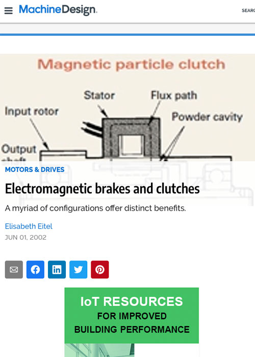
How it Works – Magnetic particles (very similar to iron filings) are located in the powder cavity. Without any voltage/current, they sit in the cavity; however, when voltage/current is applied to the coil, the magnetic flux that is created, tries to bind the particles together, almost like a magnetic particle slush. As the voltage/current is increased, the binding of the particles becomes stronger. The brake rotor passes through these bound particles. The output of the housing is rigidly attached to some portion of the machine. As the particles start to bind together, a resistant force is created on the rotor, slowing, and eventually stopping the output shaft.

Introduction – These are a true electromagnetic brake. Electrical hysteresis, although low in torque, units have an extremely wide controllable torque range. Since these units can be controlled precisely, they are ideal for test stand applications where variable controlled torque is required. Since drag torque is minimal, these units offer the widest available torque range of any of the hysteresis products. Most applications involving powered hysteresis units are in test stand requirements.
How it Works – When current/voltage is applied to the field, it creates an internal magnetic flux. That flux is then transferred into a hysteresis disk passing through the field. The hysteresis disk is attached to the brake shaft. A magnetic drag on the hysteresis disk allows for a constant drag, or eventual stoppage of the output shaft.
When current/voltage is removed from the brake, the hysteresis disk is free to turn, and no relative force is transmitted between either member. Therefore, the only torque seen between the input and the output is bearing drag. There is no other physical contact, all torque is transmitted magnetically.
Introduction – Multiple Disk brakes are used to deliver extremely high torque in a relatively small space. These brakes can be used dry or wet (oil bath). Running the brakes in an oil bath also greatly increases the heat dissipation capability, which makes them ideally suited for multiple speed gearboxes, machine tool applications and automotive transmissions.
How it Works – Multiple disk brakes operate via an electrical actuation but transmit torque mechanically. When voltage /current is applied to the brake coil, the coil becomes an electromagnet and produces magnetic lines of flux. These lines of flux are transferred through the small air gap between the field and the armature and friction disks. The attraction of the armature compresses (squeezes) the friction disks, transferring the torque from the hub to the out disks. The housing is connected to a stationary part of the machine. The brake slips until the hub and the housing RPMs are at zero RPM. This happens relatively quickly typically (.2 -2 sec).
When the current/voltages are removed from the brake, the hub is free to turn with the shaft. Separator springs hold the friction disk away from each other, so there is no contact when the clutch is not engaged, creating a minimal amount of drag.
Although the following animation is made for a clutch, the principle of operation is the same as a brake.

Introduction – Permanent magnet tension control brakes are primarily used for either overload protection as a torque limiter or to control tension of a material. These units primarily use the strength of a magnetic field to produce a drag torque. Smaller units can use a combination of permanent magnets and magnetic particle powder to control tension. These are factory set to produce a specific slip torque. These low cost torque limiters make them ideal for paper feeds, copy machines and network printers, as well as ATM’s and ticket kiosks. Larger units can have adjustable torque settings that can be changed by an end user. Since the units do not primarily rely on friction to produce torque, wear particles are not produced. This makes them ideal for any applications where frictional wear could cause contamination to either a machine or to the product that the machine is being produced, such as clean room environments, medical applications and food processing. Since there is virtually no wear in the units, they have extremely long life which makes them ideally suited for constant tensioning applications like wire winding, film and foil payouts and winders as well as screw cap torque limiters and industrial fastening machinery.
How it Works – Inside the housing of the OPL units, there is magnetic powder. The exterior of the OPL unit is steel. The magnetic particles align along the lines of flux going from the permanent magnets to the steel housing creating a magnetic loop and the particles drag against the steel housing. The strength of the magnet and the amount of particles inside the cavity determine the drag torque of each unit.
Larger OPL units use multiple magnets creating stronger bonds between the magnetic particle powder and the steel housing.
Larger permanent magnet hysteresis brakes use multiple curved segmented magnets, in opposition to each other, acting on a centered hysteresis disc which is attached to the unit’s shaft or hub. On the opposing side is an identical magnet that can be turned by around 45 degrees to go from a minimum to a maximum drag torque. In between the two magnetic discs is a hysteresis disc which is absorbed by the flux of the magnetic fields, but are held apart by a spacer.
An adjustment screw is used to hold the position of the magnets relative to each other. In a minimum torque condition the magnetic discs are aligned north to south. In this case, the flux travels straight through the hysteresis disc putting a minimum magnetic drag on the disc.
In a mid range torque condition, discs are partially rotated, so there is slightly more drag on the hysteresis disc. In the maximum torque condition, discs are rotated until the fields are directly opposing each other, so the magnetic fields bump against each other and have to travel circumferentially through the disc putting the maximum amount of magnetic drag on the disc.
A short animated movie overview that explains how an Electromagnetic Brake works